| Lesson 4 | Diagramming entities and attributes |
| Objective | Identify conventions for diagramming entities and attributes. |
Diagramming Entities and Attributes
Diagramming conventions exist for the Crowsfoot data model, also known as the Crow's Foot Notation. This is a specific method used to represent entities, attributes, and relationships in an Entity-Relationship Diagram (ERD). It's called 'Crowsfoot' due to the three-pronged shape of the symbol used to represent relationships, which resembles a bird's footprint.
In the Crowsfoot notation:
In conclusion, the Crowsfoot data model employs a clear, defined diagramming convention to visually communicate the entities, their attributes, and the relationships between them in a comprehensive and easy-to-understand manner. It's a widely adopted standard in data modeling due to its simplicity and effectiveness.
- Entities: Entities are the objects or concepts about which data is being collected. They are represented as rectangles in the diagram. The name of the entity is placed inside the rectangle and is usually a noun. For instance, 'Employee' or 'Product'.
- Attributes: Attributes are characteristics or properties that describe an entity. They are depicted as ovals connected to their respective entities by a straight line. The attribute name is placed inside the oval. For instance, 'Employee Name' or 'Product Price'. In Crow's Foot notation, key attributes (those used to uniquely identify an entity instance) are typically underlined.
- Relationships: Relationships show how entities are interconnected. They are represented as lines that connect entities. The 'crow's foot' symbol is used to indicate the 'many' side of a one-to-many (1:M) or many-to-many (M:N) relationship. If a straight line is used, it indicates 'one' or 'only one'. A circle on the line can be used to indicate 'zero' or 'optional'. Thus, you can represent cardinality and optionality in your relationships.
- Cardinality: Cardinality is represented by placing the appropriate symbols at the end of the line connecting entities. The 'crow's foot' indicates 'many' while a straight line indicates 'one'. A line with a circle at the end indicates 'zero' or 'optional'.
Here are a few examples:
- One to One (1:1): A straight line connects the entities.
- One to Many (1:M): A line with a 'crow's foot' at the end connecting to the entity representing 'many'.
- Many to Many (M:N): Typically, this is represented through an associative entity (also known as a bridge table or junction table) with 'crow's feet' at both ends of the lines connecting to the main entities.
- Zero or One (0..1): A straight line with a circle at the end.
- Zero, One, or Many (0..M): A line with a 'crow's foot' and a circle at the end.
- Associative Entities: Associative entities are used to represent M:N relationships or when additional data needs to be stored about the relationship. These are also rectangles, often drawn with rounded corners to differentiate them from other entities.
In conclusion, the Crowsfoot data model employs a clear, defined diagramming convention to visually communicate the entities, their attributes, and the relationships between them in a comprehensive and easy-to-understand manner. It's a widely adopted standard in data modeling due to its simplicity and effectiveness.
The Crowsfoot model neatly packages entities with their attributes by placing them in boxes.
There are no hard and fast rules about how these “entity packages” should look; the important thing is that the look be consistent across the diagram.
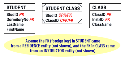
Below is an example of a common format for a Crowsfoot ER diagram, illustrating, in this case,
Below is an example of a common format for a Crowsfoot ER diagram, illustrating, in this case,
- a standard entity (STUDENT) and
- composite entity (STUDENT CLASS),

Entities
Entity names in the box are singular and often all capital letters are used. Within the box, a line separates the entity name from the list of attributes below it.
Note: Composite entities are identified by special markings in the corners of the box as show in the STUDENT CLASS above.
Note: Composite entities are identified by special markings in the corners of the box as show in the STUDENT CLASS above.
Attributes
Attributes are listed in a single column beneath the entity name. The key attribute is listed first, and is often labeled PK to indicate it is the primary key (another case where, for the sake of convenience, entities and tables share terminology). When an entity receives a PK from an associated entity, that attribute is labeled FK to indicate that it is a foreign key (in other words, the primary key from an associated entity).
Composite entities have composite primary keys, labeled CPK/FK. In the graphic above, the two attributes labeled CPK/FK indicate the two primary keys the composite entity STUDENT CLASS received to form the links to STUDENT and to CLASS.
The next lesson illustrates the constructs used to diagram types of relationships with the Crowsfoot model.