| Lesson 9 | Many-to-many Relationships (In Depth) |
| Objective | Identify many-to-many Relationships |
Identify Many-to-many Relationships
A classic example of a many-to-many relationship is this:
A student may enroll in many classes (1:M);
a class may have many enrolled students (1:N).
Question: How would I identify many-to-many Relationships based on the following ERD modeling constraints:
1. A student may enroll in many classes (1:M); 2. a class may have many enrolled students (1:N).
In the given scenario, a data designer can identify many-to-many relationships based on the following Entity-Relationship Diagram (ERD) modeling constraints:
To identify the many-to-many relationship based on these constraints, follow these steps:
By following these steps, a data designer can identify the many-to-many relationship between 'Student' and 'Class' entities based on the given constraints, and create an ERD that accurately represents the data structure in a format suitable for implementation in a relational database.
- A student may enroll in many classes (1:M);
- A class may have many enrolled students (1:N).
To identify the many-to-many relationship based on these constraints, follow these steps:
- Understand the entities and constraints: First, identify the entities involved in the relationship: 'Student' and 'Class'. Next, analyze the constraints, which state that a student can enroll in multiple classes, and a class can have multiple enrolled students.
- Determine relationship cardinality: In this case, the relationship between 'Student' and 'Class' entities is many-to-many (M:N) because multiple instances of each entity are related to multiple instances of the other entity. A many-to-many relationship occurs when instances of one entity can be associated with multiple instances of another entity, and vice versa.
- Introduce an associative entity: Many-to-many relationships cannot be directly implemented in relational databases, so a data designer must introduce an associative entity (also known as a junction table or linking table) to break down the many-to-many relationship into two one-to-many relationships. The associative entity holds the primary keys of both related entities, creating a composite primary key.
- Create the associative entity: In this scenario, create an associative entity called 'Enrollment' to represent the relationship between 'Student' and 'Class'. The 'Enrollment' entity should have the primary keys of both the 'Student' and 'Class' entities as its attributes (e.g., 'Student_ID' and 'Class_ID').
- Establish one-to-many relationships: Now, create two one-to-many relatonships:
a. Between 'Student' and 'Enrollment': A student may have multiple enrollments, but each enrollment is associated with only one student (1:M).
b. Between 'Class' and 'Enrollment': A class may have multiple enrollments, but each enrollment is associated with only one class (1:N). - Use notation to represent relationships: In the ERD, represent the one-to-many relationships using lines connecting the related entities. Add a crow's foot symbol at the end of the associative entity ('Enrollment') and a straight line or a single bar at the end of the parent entities ('Student' and 'Class') to signify the one-to-many relationships.
- Validate the relationships: Review the resulting ERD to ensure it accurately reflects the given constraints and effectively represents the many-to-many relationship between 'Student' and 'Class' entities. Consult with stakeholders and subject matter experts to confirm that the ERD meets the business requirements.
By following these steps, a data designer can identify the many-to-many relationship between 'Student' and 'Class' entities based on the given constraints, and create an ERD that accurately represents the data structure in a format suitable for implementation in a relational database.
Student Class Entities
Ad Relational Database Design
Degree of a Relationship
The degree of a relationship is the "number of entities" associated with the relationship. The n-ary relationship is the general form for degree n. Special cases are the binary, and ternary forms, where the degree is 2, and 3, respectively.
In a binary relationship, the association between two entities represents the most common type in real world modeling scenarios. A recursive binary relationship occurs when an entity is related to itself. An example might be "some employees are married to other employees". A ternary relationship involves three entities and is used when a binary relationship is not sufficient to represent your modeling scenario. Many modeling approaches recognize only binary relationships. When ternary or n-ary relationships are present in a data modeling use case, they are decomposed into two or more binary relationships.
In a binary relationship, the association between two entities represents the most common type in real world modeling scenarios. A recursive binary relationship occurs when an entity is related to itself. An example might be "some employees are married to other employees". A ternary relationship involves three entities and is used when a binary relationship is not sufficient to represent your modeling scenario. Many modeling approaches recognize only binary relationships. When ternary or n-ary relationships are present in a data modeling use case, they are decomposed into two or more binary relationships.
- Connectivity and Cardinality:
The connectivity of a relationship describes the mapping of associated entity instances in the relationship.
The values of connectivity are "one" or "many". The cardinality of a relationship is the actual number of related occurences for each of the two entities. The basic types of connectivity for relations are: 1) one-to-one, 2) one-to-many, and 3) many-to-many.
A one-to-one (1:1) relationship is when at most one instance of a entity A is associated with one instance of entity B. For example, "employees in the company are each assigned their own office. For each employee there exists a unique office and for each office there exists a unique employee. A one-to-many (1:N) relationship is when for one instance of entity A, there are zero, one, or many instances of entity B, but for one instance of entity B, there is only one instance of entity A. An example of a 1:N relationships is
a department has many employees
each employee is assigned to one department
A many-to-many (M:N) relationship, sometimes called non-specific, is when for one instance of entity A, there are zero, one, or many instances of entity B and for one instance of entity B there are zero, one, or many instances of entity A. An example is:
employees can be assigned to no more than two projects at the same time;
projects must have assigned at least three employees
A single employee can be assigned to many projects and conversely, a single project can have assigned to it many employee. Here the cardinality for the relationship between employees and projects is two and the cardinality between project and employee is three.
Many-to-many relationships cannot be directly translated to relational tables but instead must be transformed into two or more one-to-many relationships using associative entities.
Conceptual Modeling
In conceptual modeling you can combine any of the cardinality choices on either side of the relationship. There are no parents or children in a relationship such as the one shown in Figure 6-9. The entities are simply noted as being related and must be resolved by an associative or intersection entity when greater detail is necessary.
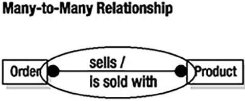
Many-to-Many Relationships
Many-to-many relationships are also very common. There is, for example, a many-to-many relationship between an order placed by an DistributedNetworks customer and the merchandise items carried by the store. An order can contain multiple items, and each item can appear on more than one order. The same is true of the orders placed with distributors. An order can contain multiple items and each item can appear on more than one order.
A many-to-many relationship exists between entities A and B if for two instances of those entities (Ai and Bi)
A many-to-many relationship exists between entities A and B if for two instances of those entities (Ai and Bi)
- Ai can be related to zero, one, or more instances of entity B and
- Bi can be related to zero, one, or more instances of entity A.