| Lesson 7 | Oracle Topology Solution — Service Names and NDM vs Spatial |
| Objective | Describe the role of service names in establishing database connectivity |
Service Names, Oracle Network Topology, and the NDM vs Spatial Distinction
This lesson has a dual purpose. The first is to explain how Oracle Net Services uses service names to establish database connectivity — the foundation of Oracle's distributed network topology solution. The second is to clarify a distinction that confused the legacy content in this module: the difference between Oracle Network topology (the Network Data Model, or NDM) and Oracle Spatial Topology (the Topology Data Model). Both use the word "topology" and both use nodes and edges, but they serve fundamentally different purposes and belong to completely different Oracle product areas. Understanding the distinction prevents the confusion that occurs when networking documentation mixes in Oracle Spatial concepts without explanation.
Part 1 — Service Names and Oracle Network Topology
In Oracle Net Services, a topology describes the overall configuration of a distributed Oracle network — every database server, client, listener, and database link that participates in the distributed environment. This global definition is what Oracle Net Services manages. It is the network topology in the traditional IT sense: which machines are connected, through what protocols, and under what service identifiers.
Oracle Net Services defines four components in a distributed network topology:
- Database servers — Oracle Database instances providing data services to clients and other database servers in the distributed environment
- Clients — applications, reporting tools, development environments, and middleware that connect to Oracle database services
- Listeners — server-side processes that accept incoming connection requests and route them to the appropriate Oracle database instance or shared server process
- Database links — schema objects that define a named connection from one Oracle database to another, enabling distributed SQL queries and cross-database transactions
What Is a Service Name?
Connectivity in an Oracle distributed network is established by defining service names — unique
identifiers that Oracle Net Services uses to locate and connect to a specific Oracle database. A service
name uniquely identifies each Oracle database in the distributed topology. It is typically the same as
the database name (ORACLE_SID) but can differ — particularly in Oracle Real Application
Clusters (RAC) environments where multiple instances serve a single database service name, and in Oracle
23ai where service names are managed through Oracle Global Data Services.
When a client requests a connection using a service name, Oracle Net translates that service name into the full connection information needed to reach the database: the protocol, host address, port number, and database service identifier. This translation is performed through one of Oracle's naming methods:
- Local naming (tnsnames.ora): The service name is looked up in the client's local
tnsnames.ora file, which contains the full connection descriptor. The traditional approach used in
Oracle 11g R2 on-premises environments:
sales = (DESCRIPTION = (ADDRESS = (PROTOCOL = TCPS)(HOST = sales-server)(PORT = 2484)) (CONNECT_DATA = (SERVICE_NAME = sales.us.example.com))) - Easy Connect Plus (Oracle 23ai recommended): The service name appears inline in
the connection string — no tnsnames.ora lookup required:
tcps://sales-server:2484/sales.us.example.com?ssl_server_dn_match=yes - Directory naming (LDAP/LDAPS): The service name is resolved through Oracle Internet Directory or a compatible LDAP server, providing centralized management of connection descriptors across all clients.
- Centralized Configuration Providers (Oracle 23ai new): Connection descriptors stored as JSON in OCI Object Storage or Azure App Configuration — eliminating distributed tnsnames.ora file management entirely for cloud and hybrid environments.
Service Name Performance Considerations
When service names are resolved through a directory server (LDAP-based naming), every client connection request involves a directory lookup. In large deployments with hundreds or thousands of concurrent connection requests, the directory server can become a performance bottleneck. Oracle Net searches for the connect identifier under a specific Oracle Context in the directory hierarchy. If the lookup takes more than approximately one second, users begin to notice degraded connection establishment times even when the database itself is performing normally.
Two approaches resolve directory naming performance problems: changing the network topology to reduce the number of hops between clients and the directory server, or implementing directory server replication so that multiple directory servers serve client lookup requests in parallel. In OCI, Oracle's Centralized Configuration Providers store connection descriptors in OCI Object Storage — a globally distributed, low-latency service that eliminates the single-server directory bottleneck entirely.
Service Names in Oracle 23ai — Modern Context
In Oracle 23ai, service names remain the foundation of database connectivity but are now managed at a higher level of abstraction through Oracle Global Data Services (GDS). GDS provides a service name layer above individual database instances — a single GDS service name can route client connections to the most appropriate Oracle database instance based on load, availability, geographic proximity, and data affinity rules. From the client's perspective, the connection string specifies a GDS service name and Oracle Net handles the resolution to the correct physical database instance transparently.
Oracle Active Directory integration in Oracle 23ai allows service names to be authenticated through Microsoft Active Directory using Kerberos — eliminating the separate Oracle Internet Directory infrastructure that earlier releases required for directory-based naming in Windows domain environments.
Part 2 — NDM vs Spatial: Clarifying the Topology Confusion
The legacy content in this module mixed Oracle Network topology concepts with Oracle Spatial Topology concepts — two entirely different Oracle capabilities that share the word "topology" and both use nodes and edges, but serve completely different purposes. The diagram below clarifies the distinction.
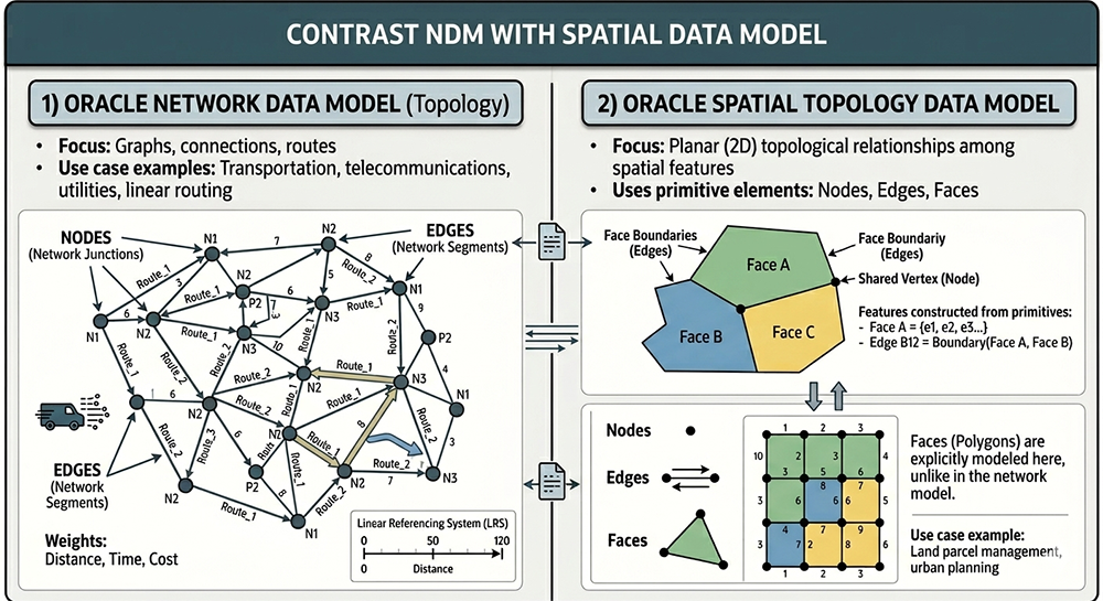
Oracle Network Data Model (NDM) — Connectivity and Routing
The Oracle Network Data Model is part of Oracle Spatial and Graph. It models networks or graphs as nodes and links (directed or undirected edges) for the purpose of connectivity analysis. The NDM is connectivity-centric and analysis-centric — its primary purpose is graph traversal, shortest path calculation, routing, reachability analysis, and flow optimization.
Key characteristics of the Oracle NDM:
- Nodes represent network junctions — intersections, substations, switching points, or any location where connections meet. In a transportation network, a node is a road intersection. In a telecommunications network, a node is a switching center.
- Edges (Links) represent the connections between nodes — road segments, power lines, fiber optic cables, or pipeline sections. Edges have weights representing distance, travel time, cost, or capacity — the attributes used by routing algorithms to find optimal paths.
- Linear Referencing System (LRS): Supports precise location along a network edge using a measured distance from the edge's start point. LRS enables address geocoding, incident location on roads, and asset management along linear infrastructure.
- Network types: The NDM supports logical networks (connectivity information only, no geometry) and spatial networks (connectivity plus SDO_GEOMETRY for nodes and edges). A spatial network can optionally be built on Spatial Topology geometries — the one scenario where NDM and the Spatial Topology Data Model interact.
Typical NDM use cases include transportation networks (road routing, multimodal transit, rail),
utility networks (electricity distribution, water supply, telecommunications), logistics and supply
chain optimization, and social network analysis. The NDM is the Oracle technology behind
SDO_NET_MEM network analysis operations and Oracle Spatial's routing engine.
Oracle Spatial Topology Data Model — Planar Integrity
The Oracle Spatial Topology Data Model is a completely different Oracle Spatial capability. Its purpose is to model and maintain planar (2D) topological relationships among spatial features with strict boundary integrity — no gaps between adjacent polygons, no overlapping boundaries, automatic update of all adjacent features when a shared boundary is moved.
The Spatial Topology Data Model uses three primitive elements:
- Nodes — point geometries representing shared vertices between edges. Every node has a coordinate pair describing its spatial location. Two or more edges meet at every non-isolated node. An island node is a node isolated within a face with no bounding edges.
- Edges — line geometries bounded by two nodes (start/origin node and end/terminal node). Each edge lies between exactly two faces and maintains references to both. The direction of an edge (positive or negative) determines which face is on its left side and which is on its right — critical for maintaining topological consistency. An island edge is an edge isolated within a face.
- Faces — polygon geometries representing areas bounded by edges. Every topology includes F0 — the universal face that contains everything else and has no geometry of its own (face ID value of -1). Faces are explicitly modeled in the Spatial Topology Data Model, unlike in the NDM where faces are not a primary element.
Topological relationships in the Spatial Topology Data Model remain constant when the coordinate space is deformed — the contains, touches, overlaps, and covers relationships between features are preserved regardless of coordinate precision or projection changes. This makes the Spatial Topology Data Model appropriate for cadastral (land parcel) management, administrative boundary datasets, census geographic data, and any application requiring strict planar topology enforcement.
The Primary Difference — Summary
The primary difference between Oracle NDM and Oracle Spatial Topology is purpose:
- Use NDM when the requirement is connectivity analysis — finding routes, optimizing paths, analyzing network flow, or modeling how things are linked for traversal. Transportation networks, utility networks, and logistics systems are NDM problems.
- Use Spatial Topology when the requirement is planar integrity — maintaining shared boundaries without gaps or overlaps, editing adjacent features consistently, or querying spatial relationships (contains, touches, overlaps) with topological correctness. Cadastral systems, census geography, and administrative boundary datasets are Spatial Topology problems.
Both models use nodes and edges, which is the source of the confusion in the legacy content. Oracle's official documentation explicitly notes that the hierarchy concepts of the two models are similar but have important structural differences — particularly the role of faces, which are a first-class element in the Spatial Topology Data Model but are not a primary element in the NDM.
For this module — Oracle Network Topology — the relevant model is the NDM and Oracle Net Services network topology, not the Spatial Topology Data Model. The Spatial Topology Data Model content that appeared in Lessons 3 and 7 of the original module was incorrectly placed and has been removed from those lessons. It is documented here in Lesson 7 solely to explain the distinction and prevent future confusion. The next lesson continues the examination of Oracle's network topology solution with the role of database links in establishing database connectivity.