| Lesson 3 | Relational Theory |
| Objective | Entity relationship diagram as relational notation. |
Relational Notation: How to Read Tables, Keys and References
Relational notation writes a table schema as its name followed by attributes in parentheses. For example, Customer(CustomerID, CustomerName) names the relation Customer, lists its two attributes, and underlines the chosen primary key.
A relation corresponds to a table, an attribute to a column, and a tuple to a row. This lesson uses underlining for primary keys and an explicit reference statement for foreign keys. Textbooks and tools vary, so always state the convention.
Compact notation describes structure; it does not show the table's current rows. To implement it, also specify domains or data types, required values, uniqueness, and business constraints.
Relational Constraints and Analysis
In the preceding course Relational Database Design, you created an Entity Relationship diagram to track the products offered by and orders placed with Stories on CD, Inc. - a fictional company that sells books on CD principally by mail order. In this module you will use a modified version of that ER diagram[1] to derive the database objects used to represent CDs, distributors, and orders in the database.
When you begin to design the structure of your database, you represent entities as relations. A relation to store data about items stocked by Stories on CD, Inc. might be expressed in relational notation as follows:
CD (CDNo, CDTitle, DistID, RetailPrice, AgeGroup, Description)
In this notation, CDNo is the primary key (underlined) and DistID is a foreign
key referencing DISTRIBUTOR.DistID. This course sometimes uses a dotted underline for a foreign key; the explicit reference removes any ambiguity. Listing keys first is a presentation convention.
Write the relationship explicitly:
CD.DistID references DISTRIBUTOR.DistID
Each CD: zero or one distributor.
Each distributor: zero, one, or many CDs.
This example permits an unassigned CD because DistID is nullable. DistID is not unique in CD, so multiple CDs can reference the same distributor. Add NOT NULL if every CD must have a distributor.
When transitioning from conceptual models to physical schemas, providing explicit DDL is practical. The SQL DDL equivalent for the CD entity is:
CREATE TABLE DISTRIBUTOR (
    DistID INT NOT NULL PRIMARY KEY,
    DistName VARCHAR(100) NOT NULL
);

CREATE TABLE CD (
    CDNo        INT NOT NULL PRIMARY KEY,
    CDTitle     VARCHAR(255) NOT NULL,
    DistID      INT,
    RetailPrice DECIMAL(10, 2),
    AgeGroup    VARCHAR(50),
    Description VARCHAR(2000),
    FOREIGN KEY (DistID) REFERENCES DISTRIBUTOR(DistID)
);
Relational Notation Explained
Relational notation is a compact way to represent the structure of data during the data modeling process. Its purpose is to describe entities (tables), their attributes (columns), and relationships (associations) in a format that is compact, unambiguous, and ready for implementation.
The conventions used here are:
- Begin with the relation (table) name.
- List the primary key attribute(s) first, underlined.
- List all remaining attributes after the primary key.
- Identify foreign keys with an explicit reference; a dotted underline may supplement it.
- Format:
TableName (PK_attribute, attribute2, FK_attribute)
Relational notation serves five purposes in the data modeling process:
-
Represents entity structure clearly. The notation specifies entity names (which become
tables), attributes (which become columns), primary keys, and foreign keys in a single compact line.
For example:
Customer(CustID, Name, Address) Orders(OrderID, OrderDate, CustID) Orders.CustID references Customer.CustIDHereCustIDis the primary key inCustomer, andCustIDinOrdersis a foreign key referencingCustomer. - Documents references. Foreign-key placement identifies the referencing table, but cardinality also depends on uniqueness and nullability. State those constraints separately. A many-to-many association maps to an intersection table.
- Supports logical to physical design. Relational notation bridges the gap between the conceptual ERD and the physical SQL schema. DBAs and developers can generate CREATE TABLE scripts and define constraints after adding domains, nullability, uniqueness, and other business rules.
- Simplifies communication. The notation provides a concise shared language that data modelers, database designers, developers, and business analysts can all read and use to review a schema without needing a graphical tool.
- Enables validation and normalization. Relational notation makes it easier to spot potential redundancies and document constraints. Verifying normal forms also requires business rules and functional dependencies; a column list alone is insufficient.
| Function | Description |
|---|---|
| Structure Definition | Lists tables and their attributes in a compact textual format |
| Key Identification | Marks primary and foreign keys explicitly |
| Relationship Mapping | Shows how tables relate through foreign key placement |
| Bridge to SQL | Provides the direct foundation for CREATE TABLE statements |
| Validation Aid | Helps normalize and verify model correctness before implementation |
The StreamingAsset Entity
Note the structural similarities between the CD relation shown above and the updated StreamingAsset entity in the project ER diagram. The StreamingAsset entity reflects a modernized version of the original domain, adapted for digital streaming platforms:
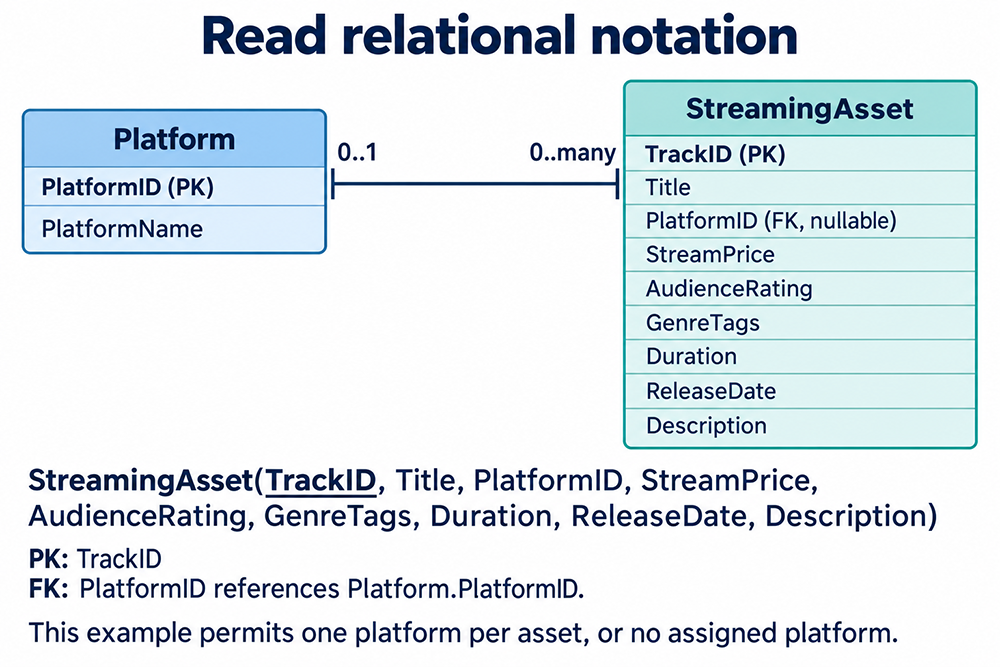
In relational notation this entity would be expressed as:
StreamingAsset (TrackID, Title, PlatformID, StreamPrice, AudienceRating, GenreTags, Duration, ReleaseDate, Description)
The structure mirrors the CD relation: a primary key leads the listing, a foreign key references another table (Platform), and descriptive attributes follow. This consistency of form across different domains is one of relational notation's primary strengths. If an asset can appear on multiple platforms, use an AssetPlatform associative table instead. If individual genres must be queried and constrained, model Genre and AssetGenre rather than a list in GenreTags.
Relational Data Modeling vs. Conceptual Modeling
The difference between relational data modeling and conceptual modeling lies primarily in their level of abstraction, purpose, and the artifacts they produce. Understanding the distinction is important because the two activities happen at different stages of the DBLC and serve different audiences.
Conceptual Modeling
Conceptual modeling is a high-level, technology-agnostic process that defines what the system should contain. It focuses on understanding and representing business requirements and real-world entities without concern for how those entities will be implemented in a specific DBMS.
The purpose of conceptual modeling is to capture business concepts and rules, define entities, attributes, and relationships at a semantic level, and act as a communication bridge between business stakeholders and technical teams. The primary artifact is the Entity-Relationship Diagram (ERD) at a conceptual level, sometimes supplemented by UML class diagrams. Conceptual models can include business identifiers and cardinality constraints. They normally omit SQL column definitions and DBMS storage details, emphasizing business meaning instead.
Conceptual modeling is the important first phase in designing a successful database application. A database application encompasses both the database itself and the associated programs that implement queries and updates. A banking application, for example, includes programs for deposits and withdrawals with user-friendly GUI forms for end users. The design and testing of those application programs has traditionally been considered part of software engineering, but database design methodologies and software engineering methodologies are strongly intertwined in most modern design tools.
This module develops relational structures and constraints from conceptual design, using the Entity-Relationship model - a widely used high-level conceptual data model whose concepts are employed by most database design tools. The ER model provides data-structuring concepts, constraints, and ER diagram notation for designing conceptual schemas.
Relational Data Modeling
Relational data modeling is a logical and technical activity that transforms the conceptual model into a format ready for implementation in a relational database system. It is a collection of processes and techniques that records the inventory, shape, size, contents, and rules of data elements within a business process scope. Despite the name, a database is not merely a collection of data - it is a collection of facts, or more precisely, true propositions about the domain it models.
Logical relational modeling defines relations, attributes, domains, keys, and constraints and analyzes their dependencies. It can remain independent of a particular DBMS. Physical design then selects DBMS-specific types, indexes, storage, and SQL syntax. Normalization targets redundancy and update anomalies, not an automatic performance improvement.
Elements to make explicit when developing the relational schema:
- Domain - the type of data values permitted for each attribute.
- Primary key - the field or combination of fields that uniquely identifies each record in a table.
- Foreign key - the field or combination of fields used to link tables; a corresponding primary or eligible unique key exists in the referenced table.
- Data redundancy - duplication of data in a database, which normalization is designed to eliminate.
Comparison
| Feature | Conceptual Modeling | Relational Data Modeling |
|---|---|---|
| Abstraction Level | High | Medium to low |
| Focus | Business concepts | Database structure |
| Artifacts | ERDs, entity and relationship specs | Relations, keys, domains and constraints; DDL at implementation |
| Users | Business analysts, data architects | Database designers, developers |
| Keys and Constraints | Business identifiers and relationship constraints | Fully defined (PK, FK, CHECK, etc.) |
| Technology Specific | No | Relational, but not necessarily DBMS-specific |
| Normalization | Not applicable | Highly relevant |
A concrete example illustrates the transition between the two levels:
Conceptual: "A Customer places Orders. Each Order contains one or more Products."
Relational excerpt: This SQL implements the customer/order relationship only. Order lines and products require additional tables; the example does not enforce at least one product per order.
CREATE TABLE Customer (
    CustomerID INT NOT NULL PRIMARY KEY,
    Name       VARCHAR(100)
);

CREATE TABLE Orders (
    OrderID    INT NOT NULL PRIMARY KEY,
    CustomerID INT NOT NULL,
    FOREIGN KEY (CustomerID) REFERENCES Customer(CustomerID)
);
Other Elements of Relational Constructs
The relational notation examples above focus on the primary key and attribute listing. Other elements of relational constructs - the data domain of each field, the primary key of each relation, and any foreign keys - will each be covered in detail later in this module. Translating an ER diagram into relational notation[2] is a standard step in the logical design stage of the database life cycle.
Once relational notations have been created from the entities in your ER diagram, you can analyze them with an eye toward three goals:
- Ensuring that information is delivered in a consistent manner across all relations.
- Eliminating data redundancy - duplicate data stored in multiple places.
- Preserving existing data when deleting unwanted data from the database.
It is possible to perform the analysis in this module and the next using entities as they appear in the ER diagram, but representing entities in relational notation makes the task easier in three important ways:
- A text format is far more compact than a graphical representation, making it practical to work with many relations simultaneously on a single page.
- Concepts covered later in this course, such as functional dependencies and transitive dependencies, are customarily written and are easier to explain using relational notation.
- If you continue studying database design beyond this course, you will almost certainly encounter relational notation in textbooks, academic papers, and professional documentation.
Being able to read and write relational notation is a valuable and transferable skill. Relations are expressed in a shorthand called relational notation - a textual interpretation of the ER diagram that makes the structure of the database explicit, compact, and implementation-ready. The next lesson outlines the characteristics of tables, which are the objects that store database data.