| Lesson 6 | Diagramming types of participation |
| Objective | Identify the symbols for diagramming types of participation. |
Diagramming Types of Participation
In data modeling, participation refers to the involvement of an entity type in a relationship type. The types of participation are typically categorized as either "total" or "partial". Total participation means that every instance in the entity set participates in at least one relationship in the relationship set. Partial participation means that not all instances in the entity set are necessarily involved in the relationship.
During the data modeling process, Entity-Relationship Diagrams (ERDs) are often used to illustrate these participation types.
Optionality is another concept closely tied with participation. If an entity's participation is optional in a relationship, it means instances of that entity may or may not participate in the relationship. This is usually represented by a circle ('o') placed on the relationship line closest to the optional entity. These diagramming conventions for total and partial participation in ERDs are integral for correctly representing the cardinality and participation of relationships during the data modeling process. They provide clarity and precision in defining how entities interact and relate to each other within the modeled system.
- Total Participation: Total participation is depicted by a double line connecting the entity to the relationship. It denotes that every instance of that entity is involved in the relationship. For example, in a relationship between 'Student' and 'Course' with a 'Registers' relationship type, if every student must register for at least one course, then the 'Student' entity would be connected to the 'Registers' relationship with a double line, indicating total participation.
- Partial Participation: Partial participation is shown by a single line connecting the entity to the relationship. It indicates that not all instances of the entity are required to participate in the relationship. For instance, in the same 'Student'-'Course' relationship, if not all courses are necessarily registered by a student, then the 'Course' entity would be connected to the 'Registers' relationship with a single line, indicating partial participation.
Optionality is another concept closely tied with participation. If an entity's participation is optional in a relationship, it means instances of that entity may or may not participate in the relationship. This is usually represented by a circle ('o') placed on the relationship line closest to the optional entity. These diagramming conventions for total and partial participation in ERDs are integral for correctly representing the cardinality and participation of relationships during the data modeling process. They provide clarity and precision in defining how entities interact and relate to each other within the modeled system.
The following series of images describe the following relationship types:
- 1:1,
- 1:N, and
- resolved M:N
Participation Symbols and ER diagrams

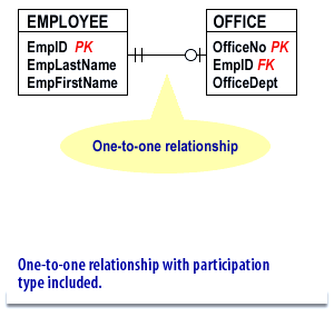
This diagram represents a one-to-one relationship between two database tables: `EMPLOYEE` and `OFFICE`. It also includes participation type notation.
🗂️ Table Structures and Attributes
EMPLOYEE
EmpID(PK): Primary KeyEmpLastName: Employee's last nameEmpFirstName: Employee's first name
OFFICE
OfficeNo(PK): Primary KeyEmpID(FK): Foreign Key referencingEMPLOYEE.EmpIDOfficeDept: Department located in the office
🔗 Relationship Analysis
- Type: One-to-One (
1:1) - Connection: Each
EMPLOYEEis assigned at most oneOFFICE, and eachOFFICEis assigned to exactly oneEMPLOYEE. - Participation:
- The line shows total participation on the OFFICE side (indicated by the double line next to OFFICE), meaning every OFFICE must be associated with an EMPLOYEE.
- The EMPLOYEE side shows optional participation (indicated by the single line), meaning an EMPLOYEE may or may not be assigned an OFFICE.

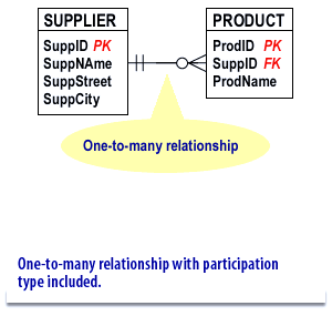
This diagram illustrates a one-to-many relationship between two database tables: `SUPPLIER` and `PRODUCT`, including participation type notation.
🗂️ Table Structures and Attributes
-
SUPPLIER
SuppID(PK): Primary KeySuppName: Supplier's nameSuppStreet: Supplier's street addressSuppCity: Supplier's city
-
PRODUCT
ProdID(PK): Primary KeySuppID(FK): Foreign Key referencingSUPPLIER.SuppIDProdName: Product name
🔗 Relationship Analysis
- Type: One-to-Many (
1:N) - Direction:
- One
SUPPLIERcan provide manyPRODUCTs. - Each
PRODUCTis supplied by exactly oneSUPPLIER.
- One
- Participation:
- The PRODUCT side shows total participation (double line), meaning every PRODUCT must be associated with a SUPPLIER.
- The SUPPLIER side shows optional participation (single line), meaning a SUPPLIER may or may not currently supply any PRODUCTs.

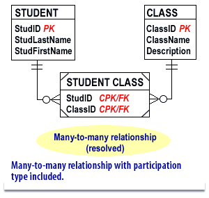
Based on the diagram, which illustrates a many-to-many relationship between two primary entities bridged by an associative table—the following analysis describes the tables, their attributes, and the relationships:
🗂️ Table Structures and Their Attributes
-
Primary Table 1: STUDENT
- StudentID (Primary Key): Uniquely identifies each student.
- StudentName: The name of the student.
- Additional attributes: May include other fields such as DateOfBirth, Email, etc.
-
Primary Table 2: COURSE
- CourseID (Primary Key): Uniquely identifies each course.
- CourseName: The title or name of the course.
- Additional attributes: Could include information like Credits, Department, etc.
- StudentID (Foreign Key): References STUDENT.StudentID.
- CourseID (Foreign Key): References COURSE.CourseID.
- Composite Primary Key: Typically, the combination of StudentID and CourseID ensures that each student–course pair is unique.
- Additional relationship attributes: May include fields such as EnrollmentDate, Grade, or Status that capture details about the enrollment itself.
🔗 Relationship Analysis
This design allows the database to efficiently manage student enrollments in various courses while capturing both the individual details of students and courses as well as the specific instances when students take courses.
Database Participation Types

🗂️ Table Structures and Attributes
-
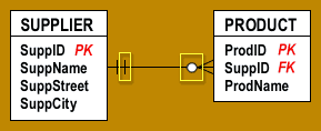
SUPPLIER
SuppID(PK): Primary Key; uniquely identifies each supplierSuppName: Name of the supplierSuppStreet: Street address of the supplierSuppCity: City where the supplier is located
-
PRODUCT
ProdID(PK): Primary Key; uniquely identifies each productSuppID(FK): Foreign Key referencingSUPPLIER.SuppIDProdName: Name of the product
🔗 Relationship Analysis
- Type: One-to-Many (
1:N) -
Direction:
- One
SUPPLIERcan supply manyPRODUCTs. - Each
PRODUCTis associated with exactly oneSUPPLIER.
- One
-
Participation:
- The symbol near
PRODUCTshows total participation (every product must have a supplier). - The symbol near
SUPPLIERshows optional participation (a supplier may or may not currently be linked to any product).
- The symbol near
- Vertical line next to Supplier: The short vertical line close to the SUPPLIER entity indicates a mandatory relationship for SUPPLIER.
- Circle next to Product: The circle symbol, indicating optional participation, is close to the PRODUCT entity, which indicates that PRODUCT is the optional (weak) entity.
- Defining Deletion Rule for Each Relationship
The first characteristic you will establish for the relationship is a deletion rule. This rule determines what your RDBMS should do when you place a request to delete a given record in the parent table of the relationship. Deletion rules are crucial to relationship-level integrity because they help guard against orphaned records, which are records in the child table that have no relationship whatsoever to any records in the parent table. These are the five types of deletion rules you can define and the actions the RDBMS should take when a given rule is in force.
- Deny: The RDBMS will not delete the record in the parent table, but will instead keep the record and designate it as “inactive.”
- Restrict: The RDBMS will not delete the record in the parent table if related records exist in the child table. You must have the RDBMS delete all of the related records in the child table before you can have it delete the record in the parent table.
- Cascade: The RDBMS will take two specific actions: It will delete the record in the parent table, and it will also automatically delete all related records in the child table.
- Nullify: The RDBMS will delete the record in the parent table and will then update the foreign key values of related records in the child table to null. If you are going to use this deletion rule, you must modify the foreign key’s field specifications and set the Null Support logical element to "Nulls Allowed.:
- Set Default: The RDBMS will delete the record in the parent table and will then update the foreign key values of related records in the child table to the current Default Value logical element setting in the foreign key’s field specifications. Obviously, you must
ER Diagram Participation - Exercise
Before moving on to the next lesson, click the Exercise link below to check your mastery of relationship constructs and participation symbols.
ER Diagram Participation - Exercise
The next lesson discusses the importance of meeting again with the database's eventual end users to determine if any revisions to the completed ER diagram are needed.
ER Diagram Participation - Exercise
The next lesson discusses the importance of meeting again with the database's eventual end users to determine if any revisions to the completed ER diagram are needed.