| Lesson 5 | Diagramming types of relationships |
| Objective | Identify the constructs for diagramming relationship types in Crow’s Foot notation. |
Diagramming Relationship Types
Crow’s Foot ERDs express two things on each end of a relationship line: cardinality (max) and modality/participation (min). You read them at the ends nearest the entities:
- Max (cardinality):
|= one,<= many - Min (participation):
|= at least one (mandatory),O= zero allowed (optional)
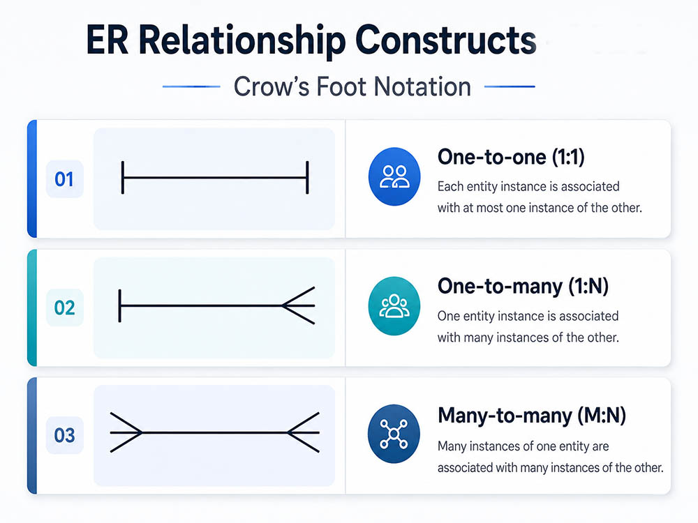
|-|), 1:N (|-<), and M:N (<->, not implementable directly and must be resolved).
Three-pronged “Crow’s Foot” symbol
The three prongs represent “many.” The opposite end uses | (one) and optionally O (zero) to express minimum participation.
OFFICE |-O< EMPLOYEE = each employee must belong to exactly one office (mandatory one), while an office may have zero or many employees (optional many).
Four relationships shown with Crow’s Foot
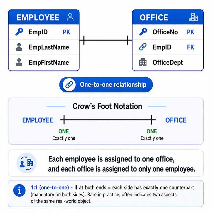
|| at both ends = each side has exactly one counterpart (mandatory on both sides). Rare in practice; often indicates two aspects of the same real-world object.
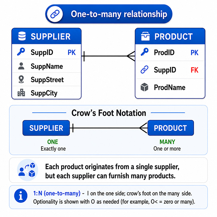
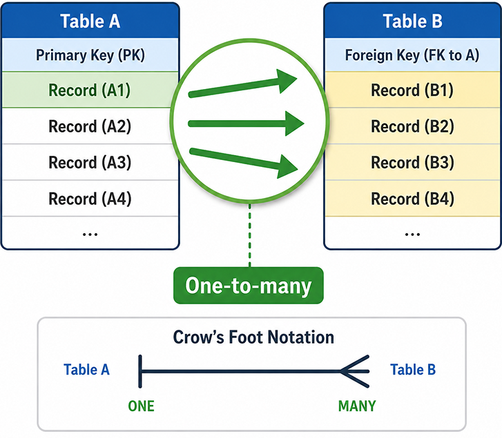
| on the one side; < on the many side. Optionality is shown with O as needed (e.g., O< = zero or many).
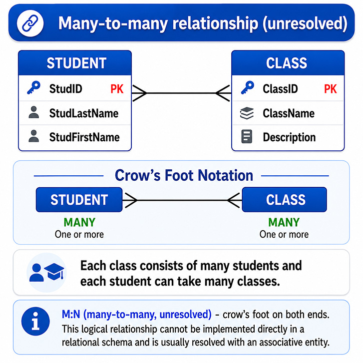
<-> logically, but cannot be implemented directly in a relational schema.
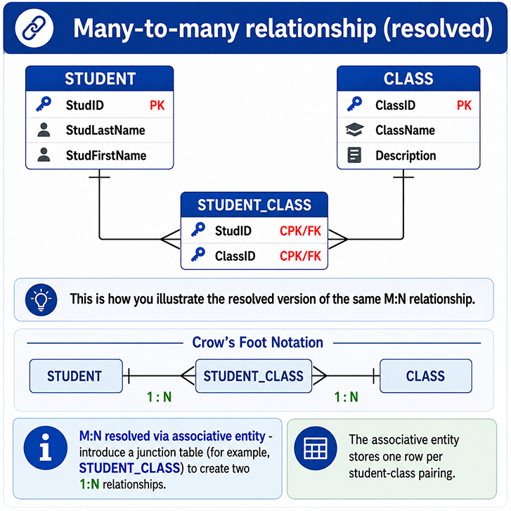
STUDENT_CLASS) to create two 1:N relationships:
STUDENT |-< STUDENT_CLASS >-| CLASS
Reading and ASCII cues
Max (cardinality): | = one, < = many
Min (participation): | = mandatory, O = optional

Examples:
1:1           |-|
1:N           |-<
0..N          O-<
0..1          O-|
M:N (logical) <->   -- requires a junction table
SQL patterns for each relationship
1) 1:1 (two common implementations)
Shared PK variant (tight coupling):
CREATE TABLE person (
  person_id NUMBER GENERATED BY DEFAULT AS IDENTITY PRIMARY KEY,
  name      VARCHAR2(100) NOT NULL
);

CREATE TABLE passport (
  person_id NUMBER PRIMARY KEY,                         -- shared PK
  number    VARCHAR2(30) UNIQUE NOT NULL,
  issue_dt  DATE NOT NULL,
  CONSTRAINT fk_passport_person
    FOREIGN KEY (person_id) REFERENCES person(person_id)
);
Unique FK variant (looser coupling):
CREATE TABLE employee (
  emp_id NUMBER GENERATED BY DEFAULT AS IDENTITY PRIMARY KEY,
  last_name  VARCHAR2(60) NOT NULL
);

CREATE TABLE office (
  office_id NUMBER GENERATED BY DEFAULT AS IDENTITY PRIMARY KEY,
  emp_id    NUMBER UNIQUE NOT NULL,                     -- enforces 1:1
  room_no   VARCHAR2(20) NOT NULL,
  CONSTRAINT fk_office_employee
    FOREIGN KEY (emp_id) REFERENCES employee(emp_id)
);
2) 1:N (mandatory one on child; optional many on parent)
CREATE TABLE supplier (
  supplier_id NUMBER GENERATED BY DEFAULT AS IDENTITY PRIMARY KEY,
  supplier_code VARCHAR2(20) UNIQUE NOT NULL,
  name          VARCHAR2(120) NOT NULL
);

CREATE TABLE product (
  product_id  NUMBER GENERATED BY DEFAULT AS IDENTITY PRIMARY KEY,
  supplier_id NUMBER NOT NULL,  -- mandatory one
  sku         VARCHAR2(40) UNIQUE NOT NULL,
  title       VARCHAR2(120) NOT NULL,
  CONSTRAINT fk_product_supplier
    FOREIGN KEY (supplier_id) REFERENCES supplier(supplier_id)
);
3–4) M:N unresolved → resolved with junction
CREATE TABLE student (
  stud_id NUMBER GENERATED BY DEFAULT AS IDENTITY PRIMARY KEY,
  student_no VARCHAR2(20) UNIQUE NOT NULL,
  last_name  VARCHAR2(60) NOT NULL
);

CREATE TABLE class (
  class_id NUMBER GENERATED BY DEFAULT AS IDENTITY PRIMARY KEY,
  class_code VARCHAR2(20) UNIQUE NOT NULL,
  title      VARCHAR2(120) NOT NULL
);

CREATE TABLE student_class (          -- associative entity
  stud_id  NUMBER NOT NULL,
  class_id NUMBER NOT NULL,
  enroll_dt DATE DEFAULT SYSDATE,
  grade     VARCHAR2(2),
  CONSTRAINT pk_student_class PRIMARY KEY (stud_id, class_id),
  CONSTRAINT fk_sc_student FOREIGN KEY (stud_id) REFERENCES student(stud_id),
  CONSTRAINT fk_sc_class   FOREIGN KEY (class_id) REFERENCES class(class_id)
);
Elements of a Crow’s Foot ER diagram
Common visual elements and what they mean:
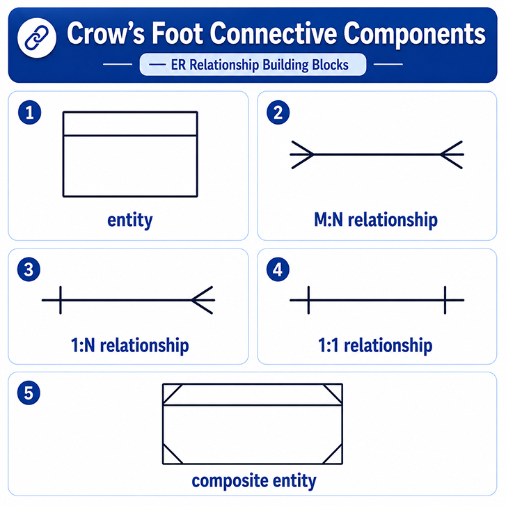
- Entity (rectangle): real-world concept; name on top, attributes below.
- 1:N:
|-<(optionality viaOas needed). - 1:1:
|-|. - M:N: logical only; use an associative entity to implement.
- Composite/associative entity: junction with a composite PK of parent FKs; may hold relationship attributes (e.g., grade).
Common pitfalls
- Modeling M:N without an associative entity.
- Confusing identifying with mandatory (identifying affects keys; mandatory affects minimum participation).
- Leaving optionality ambiguous (forgetting the
Owhen zero is allowed). - Dropping natural
UNIQUEconstraints when adding surrogate keys.
Explore more symbol details here: Crows Foot Notation.
ER diagram check
Before moving on, test yourself: given a line that reads
OFFICE |-O< EMPLOYEE, what are the min/max rules on each side?
[1]Associative Entity:An associative entity in database design is a specialized entity type that represents a many-to-many relationship between two or more other entities, effectively resolving the relationship by storing additional attributes or data about the association itself. It typically includes foreign keys referencing the primary keys of the related entities as its own primary key (often composite), allowing for the normalization of the database schema while accommodating complex relational details.