IDEF1X, Crow’s Foot, and Chen: Reading the Same ER Model
Different ER notations express the same business rules with different symbols. This page aligns three popular styles—IDEF1X, Crow’s Foot (Information Engineering), and Chen—using one shared rule:
AnOFFICEcan have zero or manyEMPLOYEEs; eachEMPLOYEEbelongs to exactly oneOFFICE.
Use the quick-compare, then dive into each notation’s essentials and how they map to relational schema.
OFFICE→EMPLOYEE): (1) IDEF1X emphasizes keys and identifying vs. non-identifying relationships; (2) Crow’s Foot encodes cardinality (one/many) and optionality (mandatory/optional) on line ends; (3) Chen shows entities (rectangles), relationships (diamonds), and can attach attributes to either.
Quick Compare
- What you see first: Keys (IDEF1X) · Line-end symbols (Crow’s Foot) · Relationship diamonds/attribute ovals (Chen).
- Best for: Standards/governance (IDEF1X) · Team communication & implementation (Crow’s Foot) · Teaching/concept discovery (Chen).
- Same rule, different cues: “one” vs “many”, “mandatory” vs “optional”, and whether a child’s identity depends on the parent.
I. IDEF1X Notation (keys and dependency)
IDEF1X distinguishes identifying (child’s PK includes parent’s PK) and non-identifying (child has its own PK) relationships. It is standards-oriented and explicit about key migration.
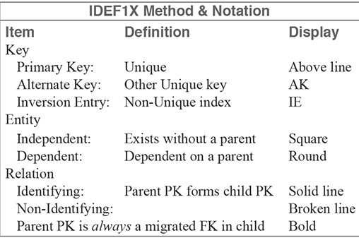
How the rule reads in IDEF1X
- Parent:
OFFICE; Child:EMPLOYEE. - Identifying line ⇒
OFFICE_IDbecomes part ofEMPLOYEE’s PK. - Non-identifying line ⇒
EMPLOYEEkeeps its own PK;OFFICE_IDis an FK only.
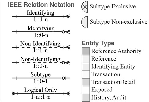
II. Crow’s Foot Notation (cardinality and optionality)
Crow’s Foot uses end-markers for maximum (|=one, <=many) and minimum (|=at least one, O=zero allowed). Read the ends nearest each entity.
- OFFICE→EMPLOYEE:
O<atEMPLOYEEside = zero or many employees per office. - EMPLOYEE→OFFICE:
||atOFFICEside = each employee must belong to exactly one office.
Relational Database Design
III. Chen Notation (entities, diamonds, attributes)
Chen shows entities as rectangles, relationships as diamonds (e.g., assign), and attributes as ovals. Cardinality (1/N) and participation (total/partial) appear near lines/ends. Relationship attributes (e.g., “since_date”) are attached to the diamond.
IEEE Relation Style: More Line Semantics
From ERD to Relational Tables
Non-identifying (common in OLTP): child has its own surrogate PK; parent PK migrates as FK.
-- Parent
CREATE TABLE office (
  office_id   NUMBER GENERATED BY DEFAULT AS IDENTITY PRIMARY KEY,
  office_code VARCHAR2(30) UNIQUE NOT NULL,
  name        VARCHAR2(100) NOT NULL
);

-- Child
CREATE TABLE employee (
  employee_id NUMBER GENERATED BY DEFAULT AS IDENTITY PRIMARY KEY,
  office_id   NUMBER NOT NULL,
  last_name   VARCHAR2(60) NOT NULL,
  first_name  VARCHAR2(60) NOT NULL,
  CONSTRAINT fk_employee_office
    FOREIGN KEY (office_id) REFERENCES office(office_id)
);
Identifying (child identity depends on parent): parent PK participates in child PK.
CREATE TABLE employee_ident (
  office_id   NUMBER NOT NULL,
  emp_no      NUMBER NOT NULL,
  last_name   VARCHAR2(60) NOT NULL,
  first_name  VARCHAR2(60) NOT NULL,
  CONSTRAINT pk_employee_ident PRIMARY KEY (office_id, emp_no),
  CONSTRAINT fk_employee_ident_office
    FOREIGN KEY (office_id) REFERENCES office(office_id)
);
Cheat Sheet: Reading the Same Rule
- IDEF1X: solid = identifying; dashed = non-identifying; watch which keys migrate and where.
- Crow’s Foot:
|/<(max),|/O(min). The||next toOFFICEmeans “exactly one office per employee.” - Chen: check 1/N markers and line styles for total vs partial participation; relationship attributes hang off the diamond.
Common Pitfalls
- Forgetting optionality (mixing up
Ovs|). - Using a direct M:N without an associative entity.
- Confusing identifying with mandatory: identifying affects keys; mandatory affects minimum participation.
- Dropping natural
UNIQUEconstraints when adding surrogate keys.
What to Use When
- Crow’s Foot: day-to-day design and reviews; concise handoff to implementation.
- Chen: pedagogy, discovery workshops, or when relationship attributes must be explicit.
- IDEF1X: regulated/standards-driven environments needing precise key/relationship semantics.
Takeaway: Learn one deeply (Crow’s Foot for practice), then use the compare above to translate the same model across notations.